
Rail Support Insulator Provider Changmei Technology: Third‑Rail Support, Insulation & Protection for Metro Power Supply
Contact Mode Determines the Support Assembly Before Individual Parts Are Chosen
Before delving into the technical specifications of individual brackets and clamp plates, engineering teams must first establish the fundamental current collection method: lower-contact or upper-contact. The direction from which the shoegear interfaces with the conductor rail completely alters the support geometry, the arrangement of the protective covers, and the necessary maintenance clearances.
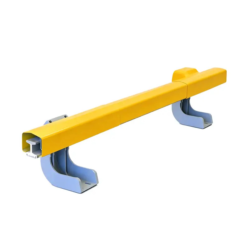
A lower-contact system, commonly applied in DC750V and DC1500V transit networks, allows the shoegear to draw current from the underside of the rail. In this configuration, the complete assembly encompasses the insulated bracket, the clamp plate, the cover bracket, and the protective cover, all oriented to leave the bottom contact surface unobstructed.
Conversely, an upper-contact system requires the shoegear to draw power from the top of the rail. While this system utilizes similar core components—brackets, clamp plates, and protective covers—their installation orientation and the geometry of the protective shielding must be completely reorganized to accommodate the upper contact interface. Establishing the contact mode and voltage class first prevents procurement teams from mistakenly optimizing components for the wrong conductor-rail architecture.
The Insulated Bracket Carries Both Position and Mechanical Load
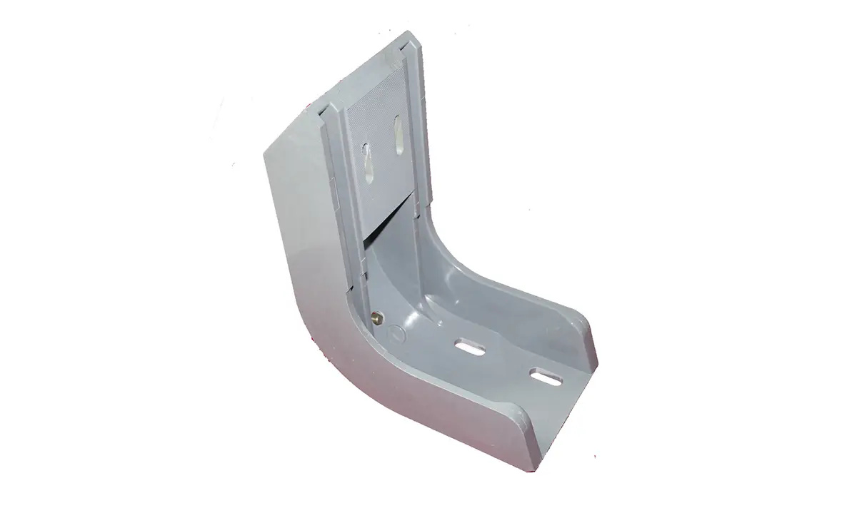
The insulated support bracket acts as the primary load-bearing and positioning spine of the conductor rail assembly. It must bear static compression, vertical loads, and horizontal working loads while simultaneously providing absolute electrical isolation from the track bed. For the lower-contact system, the engineering data mandates a static compression capacity of ≥500 kg, a vertical working load of ≥2.5 kN, and longitudinal/lateral loads of ≥2 kN.
The vertical load capacity confirms that the bracket can support the dead weight of both the conductor rail and the protective cover assembly, alongside dynamic operational forces. The longitudinal and lateral working loads are equally critical; they ensure the conductor rail maintains its exact spatial alignment when subjected to train traction forces, braking events, and lateral disturbances.
To achieve this dual role of structural strength and electrical isolation, the bracket is manufactured from a glass-fiber reinforced unsaturated polyester molding compound using a precision compression molding process. This ensures that both high mechanical rigidity and reliable dielectric strength are integrated into a single, unified composite component.
Clamp Plates Control Rail Retention at the Mechanical Interface
The core engineering responsibility of the clamp plate is to securely lock the conductor rail onto the insulated bracket. Therefore, a clamp plate must be precisely matched to the rail's cross-sectional profile, the bracket's geometry, and the planned maintenance workflow. Procurement teams must avoid selecting clamp plates based solely on generic dimensions.
Working in tandem with the bracket, the clamp plate defines the mechanical fastening interface. The pre-tension applied to the clamp and the exact contact points dictate the longitudinal and lateral stability of the rail. Consequently, clamp plates must always be evaluated in conjunction with the bracket’s working load limits and the specific rail profile drawings.
The lower-contact product series lists multiple, specific drawing numbers for brackets, claws, supports, blocks, and protective covers. This granular documentation proves that a reliable conductor rail installation relies on a multi-component assembly, rather than isolated parts. The clamp plate’s retention capability must be verified within the context of the complete, assembled structure.
Protective Covers Need Deflection and Impact Verification
A protective cover serves a much greater engineering purpose than simply acting as an anti-touch barrier. Its span length, deflection limits, and impact resistance directly dictate the physical boundaries of the third-rail protection zone. For the lower-contact system, a 5-meter span cover must restrict its maximum deflection to ≤12 mm under a 100 kg vertical static load, and must not crack or break when subjected to a 100 kg mass dropped from a height of 450 mm.
Similarly, the supporting cover bracket possesses its own independent deformation threshold, requiring a maximum deflection of ≤5 mm under a 100 kg vertical static load. These distinct metrics ensure that both the continuous cover and its localized supports are independently verified for structural integrity.
To match the distinct geometric requirements of these components, the protective cover is manufactured using a pultrusion process, which is ideal for long, continuous profiles. In contrast, the insulated bracket utilizes compression molding to achieve complex, load-bearing shapes. This dual-process approach ensures optimal manufacturing techniques are applied to each specific component type.
Flashover Ratings Set the Electrical Safety Boundary
Beyond mechanical load capacities, conductor-rail supports must establish an impenetrable electrical safety envelope. The lower-contact system provides a comprehensive electrical baseline: a power-frequency dry flashover of ≥60 kV, a wet flashover of ≥30 kV, a contamination withstand of ≥10 kV, and a lightning impulse withstand of ≥125 kV.
The significant difference between dry and wet flashover values highlights how surface moisture alters the external insulation path. For transit projects located in environments with high humidity, heavy dust, or industrial pollution, engineers must evaluate this wet margin alongside the creepage distance and the surface condition of the bracket to guarantee long-term safety.
The lightning impulse and contamination withstand ratings specifically address transient overvoltages and severe pollution scenarios. By combining these electrical thresholds with the bracket’s structural load limits, procurement teams can execute a rigorous, two-dimensional "mechanical plus electrical" acceptance process.
Custom Production and Field Support Complete the Third-Rail Package
Third-rail support assemblies are inherently project-specific because bracket height, clamp geometry, cover arrangement, contact mode, voltage class, and site interfaces can change from one line to another. Changmei Technology’s product matrix already includes multiple drawing numbers and dimensional variants, and its engineering service supports tailored solutions based on specific client requirements. This gives project teams a route from line drawings and electrical/mechanical limits to a matched support-and-protection assembly.
After the configuration is defined, batch consistency is controlled through an automated production line with capacity of about 100,000 sets per year, raw-material testing, and sampling before, during, and after production. These controls help keep brackets, clamp plates, cover supports, and protective covers aligned with the approved project configuration.
Changmei Technology extends project-specific production into installation through guidance, operator training, spare-parts support, and technical consultation. This helps metro operators keep replacement components compatible with the installed third-rail assembly. Further product details are available at https://www.changmeitech.com/.
Shaanxi Changmei Technology Co., Ltd.
Changmei Technology
email us here
Visit us on social media:
LinkedIn
Facebook
YouTube
TikTok
Legal Disclaimer:
EIN Presswire provides this news content "as is" without warranty of any kind. We do not accept any responsibility or liability for the accuracy, content, images, videos, licenses, completeness, legality, or reliability of the information contained in this article. If you have any complaints or copyright issues related to this article, kindly contact the author above.
